MEMORISED DESCRIPTION OF
COMPTOMETER's ® MECHANISM
by
Ray Mackay
![]()
| This report
consists of the thirty year old or more memory,
operations and adjustments for Felt & Tarrant Comptometers from Models J through 3D11. In
general it will also cover the repair and adjustment of
model the Model ‘H’ and will describe recalled
differences between this model and the later models.
Section will also be applicable to models ‘E’
and ‘F’ and a brief recollection of the
accumulation sections of and error control mechanisms or
these models will be given. A brief description of
recollection of a ‘so called commercial’ Model
‘A’ or wooden box models will also be given.
Although the information and ideas are provided for
enthusiasts to use freely. The material is copyrighted and therefore may not be reproduced for profit. Errors and exclusions may exist. Although endeavours have been made to provide assistance in repair work, restoration and preventative maintenance no subsequent responsibilities can be accepted. In spending the time to reproduce these details and the accompanying sketches it is hoped that some of these machines can be kept in working order for historic purposes. The record is provided as a treatise and report of what may be called a lifetimes association with these machines before moving on the their electronic counterparts and later to Computers. Hopefully, at some later date I will be allowed to provide similar guidelines for MADAS and Walther adding and calculating machines. A work on the Walther History is available through James Redin's X-Number World of Calculators Site. No responsibility can be accepted for the work as it provided merely as a historic record not an all encompassing service manual. It is passed on at this time so that the flame may not die out. My association with mechanical adding and calculating machines began circa 1954,. when I commenced working for an Australian Importer. The employer was Peacock Bros and I was placed on the payroll by a Mr. Edgar Peacock. I recall him as a elderly gentleman with a number of small books on ethics by a person called Henry Thomas Hamblyn scattered around his desk. This was a notice that effected many of the thoughts and inspirations that followed the author though his life. I also I recall he was a Czekoslovac consulate. He died only months after employing me and thus I never got to know him at all. Mr. Peacock put me under the tutelage of one, Mr. Fitzhenry a Freemason with a dedication that lead me to gain both and understanding of the mechanics of the machines, and understanding or things of the spirit and a thorough grounding in the ethic of doing ones best for the client. Many of these ‘old world’ attributed now seemingly disappearing. Mr. Peacock was replaced by Mr. S.A.Yuritta and the hundred year or more old business still trades in Oakliegh a suburb of Melbourne, Australia. |
| THE COMPTOMETER BY FELT AND TARRANT |
| A
BRIEF DESCRIPTION The Comptometer was a key driven machine consisting of a number of columns of keys numbered from one to nine. The largest of number of columns of keys the author saw was twenty columns and such machines were located in the Australia Post Office and Australian Customs Departments. The normal size of such machines was of ten and twelve columns. Because Australia worked in £’s, shilling and pence, at the time, the American built machines were built especially to cater for this type of currency. A separate section will cover this mechanism and for the main part we will concentrate on the standard machine of ten and twelve columns by nine keys. These machines being capable of addition and subtraction (using the nines complement) multiplication by repeated addition and division by repeated subtraction, again using the complement. Skilled operators were required to operate the machines and because of this ‘Comptometerists Schools’ were held in each Australian States to provide clients with a steady pool of skilled operators. In Melbourne the school was first run by Miss Doris Hedley and later by Miss Verna James. |
| THE
KEY DRIVEN MECHANISM As the machines were key driven machines we will start with a description of the ‘Key stem’ as this is where all functions originally start. The key stem was a flat pressed metal stem consisting of a key top, with the numeric value and its complement extruded into the plastic top. The key stop then being forced onto the top of the key by means of a press. Each designation from on to nine was of differing lengths. As the key was to work in a slot in a plate, designated the key plate, each key had a working area and due to the wear that the key would be subjected to this stem was of quality metal buy not hardened. In the area below the key plate the key stem had two protrusions. On to the right of the key, looking from the front, and one to the left. The right protrusion operated two levers, a segment lever and its associated lever. The left hand projection operated the key stop levers, of which there were two, designated ODD and EVEN key stop levers. The key stem was held in place by a key spring and key piece retainer. As an aside it should be noted that one of the crowning qualities bestowed upon the machines was the quality of the springs. Mr. Fitzhenry often told me how the materials qualities were tested by drilling through plate steel with the spring to assure the material retained it values. I also remember reading a similar story in one of the many Comptometerists’ Magazines lying around at the time. |
| THE
SEGMENT LEVER The Segment Lever was the lever that actually drove the accumulator pinions. Swing in an arc, a distance determined by the key pressed, this lever consisted of a series of lugs. At the front of the lever was a pinion rack that was forged on to the lever. During conversion to decimal currency in 1965/66 (?) this expensive to produce pinion rack was replaced by a punched out rack. Located immediately behind the rack was a series of saw teeth designed to stops the motion of the key stem in a definite manner to assure again the lever continuing downwards. The right hand protrusion of the key stem was stopped by the side frame plate, which was designed to stop the keys downward movement in an exact position. It should be realised that without key stop levers stopping the actual segment lever in an exact position the lever would have been able to continue ahead of the key stem when this was stopped by the frame plate. It is well to note at this stage that the accumulator wheel unit consisted of a segment lever pinion and ratchet, a lantern wheel section and carrying gear pinion. The pinion and ratchet being riveted into one piece. During the down stroke the pinion ratchet ‘free wheeled’. Accumulation actually taking place only during the up stroke of the Segment Lever. At this stage you may well ask why were there two levers and why is the second lever not mentioned. The second lever, which was positioned inside the actual segment lever was added to operate the trigger mechanism for the ‘error control’ which was required to assure operators made full keystrokes. Reasons for and operations performed by this lever will be described later. Suffice to say, at this stage, it is an inseparable part of the segment lever mechanism and the second lever controlled a trigger mechanisms bell crank in conjunction with the segment lever. |
| Let
us recapitulate The right hand protrusion of the key stem pushed down a segment lever as the key is pushed down by the operators finger. The downward movement of the key is positively stopped by a lug on the mainframe. During this downward movement the pinion ratchet (part of the accumulator) freewheels. The other part of the accumulator is stopped from turning by a backstop detent. The downward movement is finally stopped by a key stop operated by one of two key stop levers actuated by the left hand protrusion of the key stem. |
| KEYSTOP
LEVERS (ODD AND EVEN) To stop a moving lever being pushed down by an operator repeatedly, requires a sturdy and dependable stops mechanism. To this end the Comptometer used a Key stop Lever and Key Stops. Because of the difficulties associated with wear and tear when one tries to stop a moving rack. Jamming an obstruction into the fine tooth of a pinion or pinion rack being impracticable. A way had to be found to stop the lever continuing its journey after the frame stopped the key stem. On the Comptometer this was accomplished by adding a series of large saw teeth behind the segment rack of the segment lever. These large teeth faced the opposite direction to the segment lever rack and were quite substantial in size. Equally strong and substantial ‘stops’ were manufactured designed to obstruct the downward movement of the segment lever at exactly the same time as the frame stopped the key stem. Due the fact that these parts of the system would take quite a pounding and the necessity for the saw teeth to be substantial. Felt and Tarrant operated a double set of stops, one for the odd key and a second for the even keys. This not only allowed a more substantial mechanism but also allowed a more accurate positioning of the stop position itself; a definite stop capable of taking continuous pounding with minimal wear. THE SITUATION TO THIS POINT We have a segment lever operated by a key which can move a rack downwards, this rotates a pinion on a accumulator and the lever’s movement can be stopped in its downward operation in an exact position. |
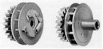
| THE ACCUMULATOR
AND PINION RATCHET We earlier described an accumulator unit with it’s pinion ratchet and such a unit is illustrated below. You will note, from left to right, the carrying gear pinion, The lantern wheel type assembly with control pins, the Ratchet Pawl, The Pawl Spring,. The unit on the extreme right being for the end column, or the highest denominator (extreme left col.,) has no segment lever and thus no ratchet.
|
| Envisage, at this stage
the pawl has clicked behind the ratchet tooth and is
engaged. The operators releases the key and the mechanism
pushed down by the keystroke is released. The engaged
pawls pushes the lantern wheel and carrying gear pinion
round by a predetermined distance as the segment lever
moves upwards under the segment levers spring tension. Once again we come up with the problem of over rotation or freewheeling. This is solved by a simple but expedient way by a roller on the bottom of the segment lever thrusting a parrots beak shaped stop, located on the carrying bell crank, into the lantern teeth of the control pints on the accumulator. Thus arresting any over rotation. More of this later under the paragraph headed ‘Carrying Bell Crank.’ CURRENT STATUS We have a gear that is capable of being rotated via a ratchet by known increments. If there are ten such increments before the gear returns to its starting point we know that we have a gears that can be described loosely as a gear with ten discrete positions ( could this be a decade counter?). If so how do we make it transfer a carry over in to the next column each time the gear makes a complete turn? How do we ascertain that any residual positions can be cleared to a zero position when required? THE ROCK FRAME |
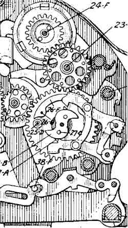
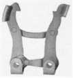
THE CARRY OVER
MECHANISM AND CARRYING BELL CRANK. The carrying bell crank is,
function-wise, a very complex piece of equipment and it
is necessary to understand what all the little bits and
pieces are, what they are for, and how they perform. At
least this is so if one wished to grasp the functions of
the unit. Let us label the parts to assist us. We can
then follow with a detailed description of each labeled
parts function. The carrying bell crank is,
function-wise, a very complex piece of equipment and it
is necessary to understand what all the little bits and
pieces are, what they are for, and how they perform. At
least this is so if one wished to grasp the functions of
the unit. Let us label the parts to assist us. We can
then follow with a detailed description of each labeled
parts function.A/ Determines rest position. B/ Sits on top of Locking Dog when no carry in play (locks) C/ Holds return spring to pull Bell Crank back to home D/ This roller sits on Escapement and follows movement of same as it rotates. Thus transferring the carry E/ Enters lantern wheel pins and stops carry motion dead in its tracks F/ Carrying Pawl. Actuates a control pin in lantern wheel G/ Stops movement of lantern wheel when segment lever roller is in up position and when in down position H holds escapement from turning as this position indicates there is an operation in action. J/ Allows carry to be inhibited for Subtraction and Division by nines complement. 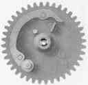  The Bell-Crank is driven by the
escapement which is connected to the carrying gear by a
spring called, naturally enough, the carrying gear
spring. The spring is ‘charged’ as the
accumulator is turned by the rack of the segment lever as
it returns from the keystroke. The Bell-Crank is driven by the
escapement which is connected to the carrying gear by a
spring called, naturally enough, the carrying gear
spring. The spring is ‘charged’ as the
accumulator is turned by the rack of the segment lever as
it returns from the keystroke. Timing is critical and to control the timing the escapement detents (odd & even, flat or hooked) release the escapement each time the gear does a half turn. When the spring has been ‘wound up’ is must hold enough latent energy to thrust the bell-crank forward when the detent releases the escapement.
The idea of
the trigger mechanism is that as the inner lever of the
Segment Lever pair goes down the top of the bell crank
moves towards the front of the machine. A horizontal
retainer resting on an upper protrusion or vertical arm
(A) on the trigger moves to teeter ready to drop behind
the horizontal retainer. As the key takes down the
Segment levers as a pair a level arm on the trigger which
rests on the pair allowing the front of the trigger to
dip. This allows the trigger itself to be latched forward
as the upper arm (A) which was teetering on the edge of
the horizontal retainer falling forward to latch there.
As the front end of the trigger is coupled via a
‘Y’ yoke to a spring loaded pair, hook and
pawl, called a pinion ratchet reverse lock and an
accumulator locking hook the mechanism is now positioned
to assure that if the operation is not completed the
accumulator will be held from coming up and adding an
amount into the carrying gear spring. As the shortened
operation would have resulted in an error the trigger is
made to hit a square shaft which in turn releases a
saddle latch under the segment levers that are in the up
position. This gives an immediate physical signal to the
operator that an error was about to take place, as all
the keys that completed the normal operation were held
from starting a new operation. TIPS
AND TRICKS TO KEEP THEM WORKING
NOTE
: Many shafts hold springs as well as acting as
pivot points for moving parts. When removing any shaft
for cleaning with smooth wet and dry emery cloth it is
necessary to follow through with a new shaft of the same
diameter; taking care not to drop any springs. Cleaning
congealed oil off shafts was a part of regular
maintenance. |
This document may be copied and released for Educational purposes. It may be copied and given to enthusiasts interested in the mechanics and remembered history of the product. It may not be produced in whole or part for the purpose of profit. |
| Copyright © 27th December 1997 Ray Mackay All rights reserved ® 1997 |

 Earlier models of the Comptometer had
permanent meshed gears and this continued up to the model
‘F’ when the idea of continuously engaged gears
was dispensed with. From the model ‘H’ onwards
all units incorporated a ‘Rock Frame’ and this
was a section that held the position of the Accumulator
and the data it represented as long as the ‘Rock
Frame’ was engaged. When the rock-frame swung out by
an actuation of the clearance handle the residual tension
in the carry over sprint returned the mechanism to a
known position we will call zero. The rock-frame
mechanism was, as far as I am aware, unique to the
Comptometer for its introduction made the complete carry
over section and accumulation storage section removable
for service.
Earlier models of the Comptometer had
permanent meshed gears and this continued up to the model
‘F’ when the idea of continuously engaged gears
was dispensed with. From the model ‘H’ onwards
all units incorporated a ‘Rock Frame’ and this
was a section that held the position of the Accumulator
and the data it represented as long as the ‘Rock
Frame’ was engaged. When the rock-frame swung out by
an actuation of the clearance handle the residual tension
in the carry over sprint returned the mechanism to a
known position we will call zero. The rock-frame
mechanism was, as far as I am aware, unique to the
Comptometer for its introduction made the complete carry
over section and accumulation storage section removable
for service.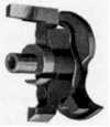
 There are exclusions to the carry taking
place. Firstly if the segment lever roll is down. The
latch, or detent, ‘H’ on the bell-crank
prevents the escapement being released until such time as
the roll returns to it’s up position. At that time
the parrots beak part of the bell-cranks stops the
rotation of the accumulator. As the escapement is
released by the parrots beak ‘G'; toggling the
detent ‘H’ the escapement turns. Flicks a
locking dog from under tail ‘B’ and as the
cranks dips the pawl ‘F’ moves forward
releasing the cranks hold on the lantern wheel pins via
the ‘parrots beak’ ‘G’ and releasing
the energy in the spring into motion, driving the bell
crank forward thus pushing the lantern wheel pin of the
next higher order. Thus a one is added to the next column
on the lefts accumulator. The column transferring from 9
to 0 completes its operation going to zero and the next
higher or increases by one significant digital. That is
increases by one completing the carry. The escapement
continues its rotation presenting a valley in it’s
cam face. The Roll ‘D’ drops into the valley
allowing the return spring attached to ‘C’ to
pull the crank back against stop ‘A’. The
Parrots Beak stop ‘G’ locks behind a lantern
wheel pin stopping any further rotation and a dog locks
under the tail ‘B’ of the bell crank holding it
in its up position.
There are exclusions to the carry taking
place. Firstly if the segment lever roll is down. The
latch, or detent, ‘H’ on the bell-crank
prevents the escapement being released until such time as
the roll returns to it’s up position. At that time
the parrots beak part of the bell-cranks stops the
rotation of the accumulator. As the escapement is
released by the parrots beak ‘G'; toggling the
detent ‘H’ the escapement turns. Flicks a
locking dog from under tail ‘B’ and as the
cranks dips the pawl ‘F’ moves forward
releasing the cranks hold on the lantern wheel pins via
the ‘parrots beak’ ‘G’ and releasing
the energy in the spring into motion, driving the bell
crank forward thus pushing the lantern wheel pin of the
next higher order. Thus a one is added to the next column
on the lefts accumulator. The column transferring from 9
to 0 completes its operation going to zero and the next
higher or increases by one significant digital. That is
increases by one completing the carry. The escapement
continues its rotation presenting a valley in it’s
cam face. The Roll ‘D’ drops into the valley
allowing the return spring attached to ‘C’ to
pull the crank back against stop ‘A’. The
Parrots Beak stop ‘G’ locks behind a lantern
wheel pin stopping any further rotation and a dog locks
under the tail ‘B’ of the bell crank holding it
in its up position. 
 A/ A prime requisite of mechanical
equipment with very close tolerance pivot points is
regular oiling with a suitable oil of the correct
viscosity. Special lubricant we recommended by the
manufacturer to service these units. Felt & Tarrant
produced a very light oil that would not congeal as long
as one adhered to a regular service routine. In Australia
we used Shell Alavania #3 on motor bearings, Shell
Ossagol V on sliding parts such as levers, pawl ends and
detents. Shell Risella 917 for pivot points and where
greasing bearing would result in sluggish action and for
Locking Dogs’, Shafts and special pivot points we
used an extremely light oil not unlike modern sewing
machine oil. I am very conscious of the necessity of
continuously lubricating shafts and pivot points with
this very light, sewing machine consistency oil and
failure to do this on a regular basis soon resulted in
machines becoming so sluggish as to be unusable by
skilled operators. Modern oils are possibly superior to
the oils and lubricants available in the fifties and
sixties, indeed I very much doubt if many of these older
lubricant are still available. Regular lubrication will
still be essential if one is to keep the machines in top
working order. Important lubrication points were.
A/ A prime requisite of mechanical
equipment with very close tolerance pivot points is
regular oiling with a suitable oil of the correct
viscosity. Special lubricant we recommended by the
manufacturer to service these units. Felt & Tarrant
produced a very light oil that would not congeal as long
as one adhered to a regular service routine. In Australia
we used Shell Alavania #3 on motor bearings, Shell
Ossagol V on sliding parts such as levers, pawl ends and
detents. Shell Risella 917 for pivot points and where
greasing bearing would result in sluggish action and for
Locking Dogs’, Shafts and special pivot points we
used an extremely light oil not unlike modern sewing
machine oil. I am very conscious of the necessity of
continuously lubricating shafts and pivot points with
this very light, sewing machine consistency oil and
failure to do this on a regular basis soon resulted in
machines becoming so sluggish as to be unusable by
skilled operators. Modern oils are possibly superior to
the oils and lubricants available in the fifties and
sixties, indeed I very much doubt if many of these older
lubricant are still available. Regular lubrication will
still be essential if one is to keep the machines in top
working order. Important lubrication points were.