 Disclaimer: The following article is not intended as
an all encompassing guide to the MADAS models 'L' through '20BTZG' but to provide
enthusiasts with a guide to 'where to look for what'. The various illustrations are taken
from copies of original drawings from the archives of H.W.Egli. The original drawings
would be held by the descendents of Hans W Egli. I expect copies will also be held by
Peacock Bros., of Melbourne. I do not have the complete set but do have twenty-three out
of a known thirty-six pages; undoubtedly there are more. Any assistance that can be given
in obtaining the missing pages would be appreciated. Disclaimer: The following article is not intended as
an all encompassing guide to the MADAS models 'L' through '20BTZG' but to provide
enthusiasts with a guide to 'where to look for what'. The various illustrations are taken
from copies of original drawings from the archives of H.W.Egli. The original drawings
would be held by the descendents of Hans W Egli. I expect copies will also be held by
Peacock Bros., of Melbourne. I do not have the complete set but do have twenty-three out
of a known thirty-six pages; undoubtedly there are more. Any assistance that can be given
in obtaining the missing pages would be appreciated. |
THE AUTHOR'S STORY
The author began working in the calculating machine industry after emigrating from the
U.K. in 1954. His first occupation in the U.K. being as a trainee in a Radar and Signals
Establishment in the county of Lancashire (now Cheshire). As with all trainees in the
1950's the apprentices were really lackies given the more mundane and dirty tasks to
complete. The more interesting tasks being left to those with the supposed skills.
Experience was gleaned from watching the experts at work when the opportunities came. The
author's dreams were of an electronics nature not of becoming a 'mechanic'.
In Australia he was first employed as a scales apprentice, a job he hated and which lasted
only months. From there he sought employment as a trainee mechanic at Peacock Bros. in
Bourke Street, Melbourne. Peacock Bros. being the Australian Importer of the Felt and
Tarrant Comptometer, the MADAS and the Walther range of office machines.
As far as mechanical training was concerned one got much of the same treatment as in the
U.K. and trainees were given the less interesting jobs until a situation came about where
one was promoted up a notch.In the author's case he was brought up by the proverbial boot
straps by an unlikely string of events. Firstly a skilled technician left to take up
another position. Simultaneously a senior trainee decided to return to England, thus a
couple of vacancies required filling promptly. The Head technician, or mechanic, was quite
elderly and only had a couple of years of working life to retirement and an opportunity
was born. The author was forced into a rapid learning curve 'to learn the ropes from the
ground up'. Mr. Fitzhenry was given the task of knocking all his knowledge into the head
of an eighteen year old whipper snapper. A task he accomplished in a short time to the
relief of the management. When Mr. Fizthenry retired the author became the "service
manager' for Peacock Bros., at a very young age.
THE VARIOUS MACHINES
The three main products sold by the office machines section of Peacock Bros. were the Comptometer, MADAS and Walther,
although there were other machines at times. For the purpose of this exercise we
concentrate on the MADAS from the above three indicated Brands. Some details of the other
units being treated elsewhere. The MADAS was manufactured by Hans.W.Egli of Switzerland.
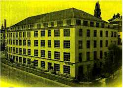
H.W.EGLI, SEESTRASSE 356 / 58, ZURICK 2 /
38, SWITZERLAND.
 The author knows little of the Egli factory in
Switzerland. In spite of frequent ambitions to visit the establishment he never satisfied
this desire. His first experience and knowledge of H.W.Egli came from the metal name
plates of Millionaire Calculators that the author started working on in 1954. Although I
had long forgotten these monsters I understand from Erez Kaplan's site (http://www.webcom.com/calc) that these machines
were first produced in 1895. Egli name plates on many MADAS machines we worked on indicate
a starting date earlier than 1920. The author knows little of the Egli factory in
Switzerland. In spite of frequent ambitions to visit the establishment he never satisfied
this desire. His first experience and knowledge of H.W.Egli came from the metal name
plates of Millionaire Calculators that the author started working on in 1954. Although I
had long forgotten these monsters I understand from Erez Kaplan's site (http://www.webcom.com/calc) that these machines
were first produced in 1895. Egli name plates on many MADAS machines we worked on indicate
a starting date earlier than 1920.
|
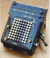
 The machines made in 1920 were not as large as the
Millionaire however, they were still large, but quite advanced. Even in 1954 these
machines were considered monsters and were picked up from their owners by van (Karrier
Bantam Van services) and brought in for service. In the earlier parts of the author's
career the MADAS were considered sophisticated machines and only selected personnel were
allowed to work on them. The machines made in 1920 were not as large as the
Millionaire however, they were still large, but quite advanced. Even in 1954 these
machines were considered monsters and were picked up from their owners by van (Karrier
Bantam Van services) and brought in for service. In the earlier parts of the author's
career the MADAS were considered sophisticated machines and only selected personnel were
allowed to work on them.
|
| CALCULATING MACHINE TYPE 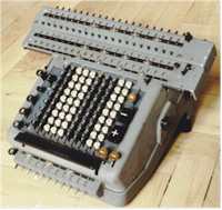 The first simple 'L' machines had all four functions but with the
control of carriage shifts and various operations being a composition of individual manual
operations. One can trace the evolution of the various MADAS models by the mechanism. The
'L' model was simple in concept and mechanically. A machine providing semi-automatic
division came later in the evolutionary process. This evolutionary process culminating in
the the model 20BTZG. The 'B' merely indicating a later Automatic multiplication
mechanism. All the machines work in cycles timed by a master cam shaft. This cam shaft was
first driven by a hand crank and then later by an electric motor installed underneath the
unit. The motor having a clutch mechanism that also allowed operation by hand crank in the
event of electrical failure. The first simple 'L' machines had all four functions but with the
control of carriage shifts and various operations being a composition of individual manual
operations. One can trace the evolution of the various MADAS models by the mechanism. The
'L' model was simple in concept and mechanically. A machine providing semi-automatic
division came later in the evolutionary process. This evolutionary process culminating in
the the model 20BTZG. The 'B' merely indicating a later Automatic multiplication
mechanism. All the machines work in cycles timed by a master cam shaft. This cam shaft was
first driven by a hand crank and then later by an electric motor installed underneath the
unit. The motor having a clutch mechanism that also allowed operation by hand crank in the
event of electrical failure.
The cam shaft determined the timing of each operation
during each cycle of the drive gear. Each standard operation was completed in this one
cycle. At first each operation was selected manually by the operator as in the case of
early and less complex models. With the introduction of machines with semi-automatic
division the machines performed several rotations of the cam shaft before coming to a stop
which required further operator intervention. The operator then moved the carriage and
repeated the operation until the process was completed. Thus the number of cycles was
dictated by the complexity and existing conditions in the calculation.
EVOLUTION OF THE MACHINE
The forgoing paragraph indicated an evolutionary process by H.W.Egli that commenced with
their earliest machines and progressed through to their most sophisticated and complex
model the BTZG. Following through the mechanics of the machines this evolutionary process
becomes most evident as controls and levers became interwoven in a complex manner around a
basic concept. Levers took on weird and wonderful shapes dictated by where they could be
located to interlink through the existing framework, mechanism and construction. You will
observe this as we progress. The first two big changes to machines by H.W.Egli will be
ignored, these being the change from the Millionaire to a MADAS with the carriage built
into its box like structure. The Millionaire was the only mechanical machine I know of
that actually multiplied by a single action multiplication mechanism. The change from the
large box like structure of the first MADAS machines into the models with a moveable
carriage at the top of the machine, this was not such a radical change as the mechanical
principles were similar and the general mechanical form remained.
DEFINITION OF REGISTERS
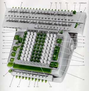 The method of defining keys and registers in this
work will adhere to the protocols used by H.W.Egli as delineated in the illustration on
the right. The registers in reference to the illustration on the right will be as
follows... The method of defining keys and registers in this
work will adhere to the protocols used by H.W.Egli as delineated in the illustration on
the right. The registers in reference to the illustration on the right will be as
follows...
| 0 |
Multiplication Register |
| III |
Keyboard or Entry Register |
| II |
Counter or dividend register |
| I |
Main or Product Register |
| IV |
Triplex or Accumulation Register |
It should be noted that not all models will have
every register and you need to use the hyperlinks throughout the text to jump to
illustrations indicating particular features and particular mechanisms. In relation to
levers and operations performed by such levers reference to the detailed picture will be
essential; at least if you wish to follow all the details.
DEFINITION OF KEY NAMES
The down arrow key transfers data from the Main Register to the multiplication register
The key with two dots, one above the other transfers data to the left of the main
register, ready for division.
The keys marked I II and III clear the Main register, the counter register, the dividend
register and the keyboard register respectively
The 'DIV' key is self explanatory
+ and - are also self explanatory
Carriage shift keys indicate direction of movement indicated by arrows.
The long Bar starts an automatic multiplication.
The key marked 0 clears the multiplication register.
The reason for the small bar to the left of the long bar escapes my recollection.
|
 METHOD OF ENTERING INFORMATION METHOD OF ENTERING INFORMATIONAll information concerning data for operations is entered into the
keyboard. The keys had a latching mechanism that prohibited more than one key being locked
down in the same column. The key marked III allowed for rapid clearance of numbers before
a new entry was put into the keyboard. Under the keytops are metal keystems that slide
into flat metal strips, two to each column; one for odd keys and one for even keys; the
arrow points to the pair of slots. These flat strips in turn move a sliding pinion,
mounted on a square shaft, into a position adjacent to the equivalent number of teeth on a
Leibniz (stepped) drum.
|
| POSITIONING KEY SELECTED PINIONS  Reference to the illustration on the left will indicate, to those not familiar
with such things, just what a stepped drum looks like. This stepped drum or Leibniz wheel
is similar to a fixed pinion gear excepting its design incorporates teeth that are
extended. Each step being incremental in length but stepping so as to make less pinion
teeth accessible to operate the gear to be driven. A somewhat clumsy description but it
fits the function quite suitably. Although the Leibniz wheel in the illustration is not in
the context we desire, it is not hard to imagine a pinion positioned on the square shaft
above our Leibniz wheel sliding over the top of various spur teeth and turning the square
shaft on which the pinion is mounted by a required 36 degrees of movement representing
1/10th turn for each tooth. This surely is a description of the required motion of such a
pair. Indeed have we not described the use of a stepped drum, or Leibniz wheel, to decide
the number of degrees turn of a shaft in increments of one tenth. Reference to the illustration on the left will indicate, to those not familiar
with such things, just what a stepped drum looks like. This stepped drum or Leibniz wheel
is similar to a fixed pinion gear excepting its design incorporates teeth that are
extended. Each step being incremental in length but stepping so as to make less pinion
teeth accessible to operate the gear to be driven. A somewhat clumsy description but it
fits the function quite suitably. Although the Leibniz wheel in the illustration is not in
the context we desire, it is not hard to imagine a pinion positioned on the square shaft
above our Leibniz wheel sliding over the top of various spur teeth and turning the square
shaft on which the pinion is mounted by a required 36 degrees of movement representing
1/10th turn for each tooth. This surely is a description of the required motion of such a
pair. Indeed have we not described the use of a stepped drum, or Leibniz wheel, to decide
the number of degrees turn of a shaft in increments of one tenth.
|
| THE POSITION SO FAR  A selected key is entered on the keyboard. A stud on the lower
end of the keystem slides down the keybar ramp into a notch in the keybar. This action
positions a sliding pinion of a square shaft over the selected position equating with the
key on a 'Leibniz Wheel'. As the drive shaft turns the Leibniz wheel actuates the pinion
turning it by 36 degrees for each spur in the selected position (36 degrees being 1/10 of
a turn). On the top end of the square shaft a fixed pinion drives the mechanism that
couples the carriage. This mechanism consists of another square shaft with a double edge
pinion as indicated on the left. This pinion/s can slide upwards or downwards as actuated
by a lever. A selected key is entered on the keyboard. A stud on the lower
end of the keystem slides down the keybar ramp into a notch in the keybar. This action
positions a sliding pinion of a square shaft over the selected position equating with the
key on a 'Leibniz Wheel'. As the drive shaft turns the Leibniz wheel actuates the pinion
turning it by 36 degrees for each spur in the selected position (36 degrees being 1/10 of
a turn). On the top end of the square shaft a fixed pinion drives the mechanism that
couples the carriage. This mechanism consists of another square shaft with a double edge
pinion as indicated on the left. This pinion/s can slide upwards or downwards as actuated
by a lever.
|
 In the upward position the motion turns a numeral wheel pinion in one
direction, in the downward position in the opposite direction. We now have a situation
where a gear can increment or decrement a numeral wheel by a selected number. Indeed we
have accumulation from one to nine and must now consider transferring a carry to the next
column as our wheel completes a cycle. In the upward position the motion turns a numeral wheel pinion in one
direction, in the downward position in the opposite direction. We now have a situation
where a gear can increment or decrement a numeral wheel by a selected number. Indeed we
have accumulation from one to nine and must now consider transferring a carry to the next
column as our wheel completes a cycle.
|
| TRANSFERRING DATA FROM PINION SHAFT
TO STORAGE REGISTER  The process of transferring data from the
pinion shaft to the carriage is illustrated on the left, as is the coupling to the numeral
wheel. Behind the numeral wheel you will note a clearance rack and also a cam marked 13.
This cam triggers a carry as the numeral wheel goes from nine to zero or zero to nine. It
is important to note the carry can be a positive or negative carry as this becomes
important later on when we get to the division process. The process of transferring data from the
pinion shaft to the carriage is illustrated on the left, as is the coupling to the numeral
wheel. Behind the numeral wheel you will note a clearance rack and also a cam marked 13.
This cam triggers a carry as the numeral wheel goes from nine to zero or zero to nine. It
is important to note the carry can be a positive or negative carry as this becomes
important later on when we get to the division process.
REMOVAL OF CARRIAGE
Some readers may have a machine whereby they wish to remove the carriage to examine the
workings described in this text. The carriage is removed by tripping a small latch to the
left of register three. The Carriage then lifts out with a slight tilt upwards towards the
back. Replacing the carriage requires an understanding of a few points. If the machine is
a 'Z' model the carry over mechanism is first lifted out of the counter register gears.
Using a piece of string looped over the carriage clearance racks the racks are pulled into
the clearance position. This means that the tens transfer cam followers are held close to
the cams and will not foul the carry over arms. The Z-mechanism is then rested just on top
of the notch in the negative carry gears and the carriage placed on in the extreme
left-hand position (all the while holding the clearance racks out with the string).
"T" models require far more attention as one must place the two markers on the
carry over cam shaft adjacent to each other and make certain the long actuating drum is in
its bias notch prior to refitting the carriage. The move really needs practice however
once learnt is never forgotten.
|
| THE TENS TRANSFER MECHANISM  We earlier mentioned a carry lever that was actuated
by the 'cam follower' tracking the position of the numeral wheel. As the wheel went from
nine to zero or visa versa the cam follower pushes in a lever as in fig 6. This lever in
turn moves a sliding pinion on the square shaft that drives the carriage numeral wheel
mechanism. When the cam follower pushes in the carry lever this pinion moves into the path
of an oscillating carry arm, the movement timing of which is controlled by the main cam
shaft via a train of gears. When this pinion moves it to the path of the carrying detent
as the detent oscillates it transfers the carry into the next higher order. Note :- this
movement takes place at a time when all other action cycles to the carriage have been
completed and thus there is no possibility of conflict. Fig 5 shows the lever and cam
shaft. The carry lever is then restored as a 'V' shaped projection of the carry lever and
is kicked out by a pin in the cam shaft drum 112a. The lever position is then retained by
the bias ball clip at the top of the carry lever. We earlier mentioned a carry lever that was actuated
by the 'cam follower' tracking the position of the numeral wheel. As the wheel went from
nine to zero or visa versa the cam follower pushes in a lever as in fig 6. This lever in
turn moves a sliding pinion on the square shaft that drives the carriage numeral wheel
mechanism. When the cam follower pushes in the carry lever this pinion moves into the path
of an oscillating carry arm, the movement timing of which is controlled by the main cam
shaft via a train of gears. When this pinion moves it to the path of the carrying detent
as the detent oscillates it transfers the carry into the next higher order. Note :- this
movement takes place at a time when all other action cycles to the carriage have been
completed and thus there is no possibility of conflict. Fig 5 shows the lever and cam
shaft. The carry lever is then restored as a 'V' shaped projection of the carry lever and
is kicked out by a pin in the cam shaft drum 112a. The lever position is then retained by
the bias ball clip at the top of the carry lever.
To recapitulate. We now have a process whereby we can enter data into a
keyboard. Transfer this data from the keyboard to the display on a movable carriage. As
the display turns from zero to nine or nine to zero we can time a carry into the next
higher order. This process giving us a mechanism by which we can add up to ten in one
column and take care of a carry. It take no stretch of the imagination to realise if we
placed ten such mechanisms (building blocks) side by side we would have available a ten
column by ten digit adding machine capable of displaying the result. We must further
recognise that as multiplication is merely repeated addition then, by moving the carriage
into various positions we actually perform a multiplication, the result depending on the
number of machine cycles in each position.
|
| COUNTER NUMBER OF CYCLES IN EACH OPERATION.  The counter register is quite a simple device in comparison with other areas.
It consists of a slotted disk attached to the numeral wheel assembly. A daisy chain rack
assembly oscillates to and from and tries to go forward and back each cycle. In the first
position, or extreme right hand position the daisy chain rack is adjusted so it always
toggles the extreme left wheel. If the position of the slot on the disk of assemblies to
the left is open these other wheels can also be toggled.If the slot in the numeral wheel
disk is available then the pawl of the daisy chain rack assembly is allowed to drop in to
this position thus actuating this position also. This allows for carries in operations of
more than ten cycles in any one position. It also provides a means for entering negative
carries across the whole counter register. In other words. If the register was clear and
you entered a minus operation all counter positions would change to nines. The counter register is quite a simple device in comparison with other areas.
It consists of a slotted disk attached to the numeral wheel assembly. A daisy chain rack
assembly oscillates to and from and tries to go forward and back each cycle. In the first
position, or extreme right hand position the daisy chain rack is adjusted so it always
toggles the extreme left wheel. If the position of the slot on the disk of assemblies to
the left is open these other wheels can also be toggled.If the slot in the numeral wheel
disk is available then the pawl of the daisy chain rack assembly is allowed to drop in to
this position thus actuating this position also. This allows for carries in operations of
more than ten cycles in any one position. It also provides a means for entering negative
carries across the whole counter register. In other words. If the register was clear and
you entered a minus operation all counter positions would change to nines.
|
 MANUAL
CARRIAGE MOVEMENTS MANUAL
CARRIAGE MOVEMENTS
We have possibly noticed previously how a pair
of pinions tied together on a square shaft can be moved upwards or downwards to engage the
drive pinion on another mechanism. By so doing the direction of the turn is forward or
reverse depending on the gear engaged. This is best illustrated in the lower illustration
to the right of "the position so far".
 A similar method can be used with a
clutch mechanism to cause a shaft to rotate to the right or left. An illustration of this
clutch mechanism is to the left. If one or the other of these clutch positions is engaged
the rollers on the cam to the right can be made to change position. As these rollers are
engaged with a large tooth rack mounted on the carriage the carriage can be made to move
to the right or to the left. To do so whilst any other operation was in progress would be
a disaster. Preventative measures are taken all over the MADAS to safeguard actions likely
to cause conflict. In the case of carriage shift you will note in the illustrations
various cam followers are made to lock out all other operations during carriage shifts. A similar method can be used with a
clutch mechanism to cause a shaft to rotate to the right or left. An illustration of this
clutch mechanism is to the left. If one or the other of these clutch positions is engaged
the rollers on the cam to the right can be made to change position. As these rollers are
engaged with a large tooth rack mounted on the carriage the carriage can be made to move
to the right or to the left. To do so whilst any other operation was in progress would be
a disaster. Preventative measures are taken all over the MADAS to safeguard actions likely
to cause conflict. In the case of carriage shift you will note in the illustrations
various cam followers are made to lock out all other operations during carriage shifts.
|
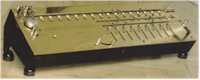
| MULTIPLICATION BY REPEATED ADDITION 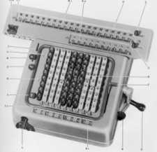 I guess every person would know the method of Multiplication by
repeated addition however for the sake of completeness I will run through it briefly. When
we multiply 12 by 12 we first multiply the first twelve by two, the answer being stored.
We step across one position as we are multiplying by tens and multiply by one. The
accumulated result being 144. On a mechanical machine such as the MADAS the same logical
process is completed mechanically. By moving the carriage one position to the right we
effectively multiply by a ten. Two positions to the right and we are multiplying by a
hundred and so on. On early machines the process requires one routine process to be
completed by an operator, this remained the situation with manual machines such as the 10R
(see right-hand inset). Later mechanisms were introduced to the existing manual machines
to make automatic multiplication possible I guess every person would know the method of Multiplication by
repeated addition however for the sake of completeness I will run through it briefly. When
we multiply 12 by 12 we first multiply the first twelve by two, the answer being stored.
We step across one position as we are multiplying by tens and multiply by one. The
accumulated result being 144. On a mechanical machine such as the MADAS the same logical
process is completed mechanically. By moving the carriage one position to the right we
effectively multiply by a ten. Two positions to the right and we are multiplying by a
hundred and so on. On early machines the process requires one routine process to be
completed by an operator, this remained the situation with manual machines such as the 10R
(see right-hand inset). Later mechanisms were introduced to the existing manual machines
to make automatic multiplication possible
|
| AUTOMATIC MULTIPLICATION  To make automatic multiplication position
one must first have a storage register to store the number by which you wished to
multiply. A sensor mechanism then becomes necessary so that the information in such a
register can be 'read'. This is not an insignificant task as we have to not only sense the
number we have to also sense the order or carriage position. H.W.Egli dropped back on the
old faithful, the Leibniz wheel however in a different form.This new form, which I will
call a stepped drum, actually uses the stepped ends of the spurs of the drum to correlate
the numeric values in the register '0' with the position of the stepped drum. To make automatic multiplication position
one must first have a storage register to store the number by which you wished to
multiply. A sensor mechanism then becomes necessary so that the information in such a
register can be 'read'. This is not an insignificant task as we have to not only sense the
number we have to also sense the order or carriage position. H.W.Egli dropped back on the
old faithful, the Leibniz wheel however in a different form.This new form, which I will
call a stepped drum, actually uses the stepped ends of the spurs of the drum to correlate
the numeric values in the register '0' with the position of the stepped drum.
|
 A pin drum was also used to sense the number of cycles the machine
needed to perform to complete a multiplication. This pin drum has multiple pins. At each
carriage shift a different pin is made to protrude. It only being possible for one to
protrude at any one time. A pin drum was also used to sense the number of cycles the machine
needed to perform to complete a multiplication. This pin drum has multiple pins. At each
carriage shift a different pin is made to protrude. It only being possible for one to
protrude at any one time. It is now essential if I
am to convey the process to the uninitiated that a scenario, or picture be painted in your
mind. Starting with the carriage in the extreme left hand position. When the
Multiplication Key is depressed,this initiates a string of mechanical processes. The part
we are interested in at this stage being the pin & pin drum. The Pin drum rotates
forward with pin one high. The pin hits the step drum on the step correlated with the
number in the multiplier register '0' position one. If the number happens to be a two then
the drum drops two tooth positions of the step drum rack. The machine cycles five times
and at each cycle the pin drum ratchets back to its starting point by one position.  At the
completion of the two cycles a carriage shift is tripped in and the carriage moves one
position to the right. Pin one drops out of play and pin two comes up. In this case we
have the one in multiplier register 'O' position 2 (the tens position). The pin drum drops
again until the newly raised pin strikes the step drum. The position being only one tooth
down. The machine takes one cycle actuating the pin drum back one position. The mechanism
senses via a sensing mechanism that no further numeric values are in the multiplier
register and either the carriage is returned to its starting point or stopped depending on
operator selectable options. The mechanism on the left illustrates the means by which the
step drum is ratcheted back to its starting position. Notice the pawl and the detent which
latches to stop over operation. Also note the stud behind a pendulum like lever that trips
(pointed to by arrow) in the next operation at the end of each recovery back to the zero
position.It should be noted many side issues take place however in consideration of size
and descriptive skill I have ignored these side issues. At the
completion of the two cycles a carriage shift is tripped in and the carriage moves one
position to the right. Pin one drops out of play and pin two comes up. In this case we
have the one in multiplier register 'O' position 2 (the tens position). The pin drum drops
again until the newly raised pin strikes the step drum. The position being only one tooth
down. The machine takes one cycle actuating the pin drum back one position. The mechanism
senses via a sensing mechanism that no further numeric values are in the multiplier
register and either the carriage is returned to its starting point or stopped depending on
operator selectable options. The mechanism on the left illustrates the means by which the
step drum is ratcheted back to its starting position. Notice the pawl and the detent which
latches to stop over operation. Also note the stud behind a pendulum like lever that trips
(pointed to by arrow) in the next operation at the end of each recovery back to the zero
position.It should be noted many side issues take place however in consideration of size
and descriptive skill I have ignored these side issues.
|
DIVISION BY REPEATED SUBTRACTION
From the above it is obvious that a number of individual processes can be automated
mechanically. We illustrated that multiplication could be automated. Historically, on the
MADAS automatic division came before automatic multiplication. It was however necessary to
first paint a picture of automation in mechanics. Division is merely repeated subtraction
using a 9's compliment. The quotient needs to be thrown up into the top left of register
one. This is accomplished by the key with the two dots. Pressing this key down instigates
a clearance action on all registers followed by a carriage shift to the extreme right. In
this position the contents of the keyboard are thrown up into register one. .The keyboard
is cleared. The operator now enters a divisor. On pressing the division key, the number in
the keyboard is added to register one, however there is a difference. Under the subheading
'the position so far' we described how a pinion engaged at 90 degrees from the top of a
gear would turn one direction whereas if this pinion was attached to a pinion that could
slide up to the bottom of the gear the direction would be reversed. In other words, how a
beveled gear engages from top to bottom of a pinion will decide the direction of the
drive. In division this mechanism is reversed and thus the increment becomes a decrement.
We take away from the extreme left hand position until a negative carry takes place across
the machine. A special division cam then institutes an add back by one followed by a
carriage shift. The routine is repeated until such time as the carriage reaches the
extreme left position. The counting register now displays the number of cycles that
existed in each column; this being the dividend or answer and the remainder remains in
register one.
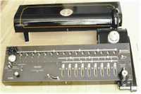
THE USE OF 'Z' MECHANISM TO TRANSFER NEGATIVE CARRY ACROSS WHOLE TWENTY COLUMNS
Later machines introduced a second counter register to the left of register (see 20BTZG
illustration) This mechanism extended beyond the normal mechanical control of the main
section of the machine. A 'Z' mechanism was introduced so that carries could be executed
across the section of carriage beyond the counting and carry levers of the main counter
mechanism. An examination of this mechanism is self explanatory and can be viewed under
the left front of the carriage whilst operating the machine manually. Its description will
be skirted.
AN OVERVIEW
An overview of the carcass mechanism less control parts is
enclosed to permit an understanding of the main frame structure of the unit.Also, several pictures showing the internals
of the MADAS 20BTZG have been included.
|
THANKS AND ACKNOWLEDGMENT
This document is a draft document. It undoubtedly contains materials of a proprietary
nature. As far as the author is aware H.W.Egli no longer make mechanical calculating
machines and never made any electronic calculating machines. It is not even known if
H.W.Egli are still in business as the author lost contact in the 1970's. Copyright exists
for some fifty years after a death of the inventor or writer. This document acknowledges
the rights of H.W.Egli to all drawings. They are provided merely to enhance an
understanding of this brief for educational purposes. The record may also assist in
preserving these historic machines.The four color
MADAS photos inserted at the beginning of this article are courtesy of Eusebio Huélamo.
|
This document is an historic record and may be copied and
released for educational purposes. It may be copied and given to enthusiasts interested in
the mechanics and remembered history of the product. It may not be reproduced in whole or
part for the purpose of profit. |
| Copyright © January, 1998 Ray Mackay All
rights reserved ® 1998 |